Simple Electronic Code Lock with Logic Gates
Welcome to John's Robotics! Today, we'll explore a basic yet fascinating project: a simple electronic code lock. This project not only helps you understand the fundamental components of electronics but also introduces you to the world of logic gates.
Overview
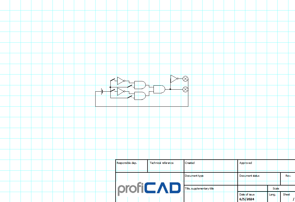
An electronic code lock is a security device that allows access only when a specific code is entered. The image below shows the electronic components used to build a basic version of such a lock. Let's break down the components and their roles in this project.
Components
- Resistors: Limit the current flow in the circuit to prevent damage to other components.
- Logic Gates: The building blocks of digital circuits, performing basic logical functions essential to digital systems.
- LEDs: Display if acces is granted.
- Switches: To enter the combination.
- Battery: Power the circuit
- Breadboard: Connect the other compoments together
Introduction to Logic Gates
Logic gates are the fundamental components of digital circuits. They take one or more binary inputs and produce a binary output. Here are the most common types of logic gates:
- AND Gate: Outputs true (1) only if all its inputs are true. Think of it as a series connection of switches.
- OR Gate: Outputs true if at least one of its inputs is true. This is like a parallel connection of switches.
- NOT Gate: Outputs the opposite of the input. If the input is true, the output is false, and vice versa.
How It Works
In our simple code lock, we use a combination of these logic gates to determine if the correct code is entered. For example, if the code is "1010", which is the correct combination, we can use two NOT gates to convert the 0s to 1s and then a handmade 4-input AND gate to check if all the inputs are now '1', if the combination is correct the green LED will light up, indicating unlocking of the device. The red LED will light up when the combination is incorrect and a NOT gate gets the off input from the 4-1nput AND gate and turn it into an on output for the red LED.
Building the Code Lock
- Set Up the Circuit: Place the components on a breadboard according to the above schematic.
- Connect the Power: Ensure all components are correctly powered.
- Test the Inputs: Enter the code using switches or buttons connected to the inputs of the logic gates.
- Check the Output: If the correct code is entered, the output will activate a relay or LED, indicating the lock is open.
*The symbol with an 'X' inside a circle means one LED with correct polarity and a resistor connected in series with it in this schematic*
The original documentation for the project (homework for the technology subject by me)(it is in greek) can be found here: *W.I.P.*.
Conclusion
This simple electronic code lock is an excellent project to get hands-on experience with basic electronics and logic gates. By understanding how these components work together, you can create more complex and secure electronic systems in the future.
Stay tuned for more exciting projects and tutorials at John's Robotics!